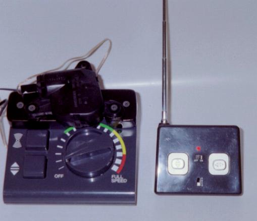
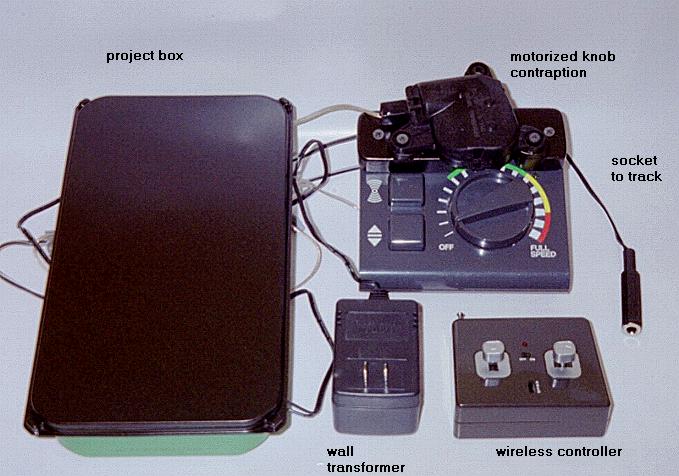
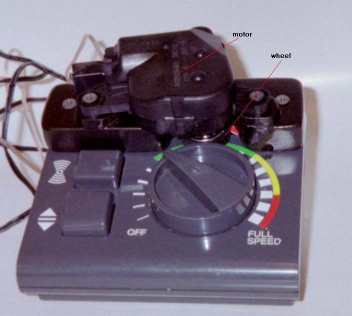
The circuit board inside an inexpensive remote controlled (RC) car has quite a lot of potential for a homemade wireless remotely controlled toy train transformer. The board is not placed in any train locomotive or piece of rollingstock, but rather kept stationary next to the transformer in a project box. In this case, a Lionel transformer that is in 2 parts, one part is the power supply and the other part has the throttle knob with direction and whistle buttons, is just right for attaching a simple motor to turn the knob, remotely, tapping into the whistle button for that feature, also.
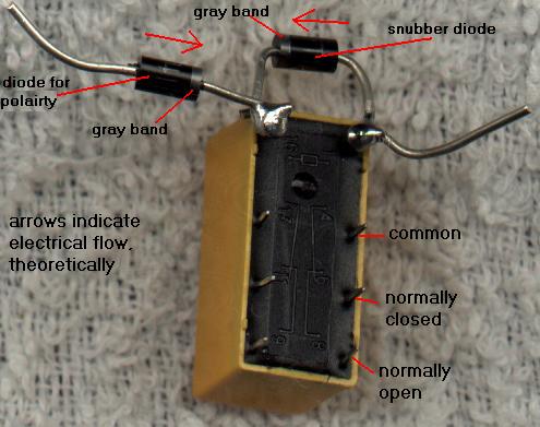
The first step is to determine what is going on inside the car. With this car there are 2 motors. One motor is for the rear wheel drive, and the other is for the steering. The circuit board just reverses the polarity of the DC to these motors to either move forward or backward, or to turn the front wheels to the right or left. There is an orange wire, coiled inside the roof of the car, that acts as an antenna, and 2 wires that come from the battery compartment. Fortunately these wires are the standard red and black for DC power, positive being the red wire. The battery compartment holds 3 AAA size cells. Figure that although they are 1.5 volts each, they are only yielding about 1.2 volts each. So, your new power supply needs to be no more than 3 VDC, or approximately 3 volts. If you can find a regulated supply (wall wart), then you are in a good position. Use a large electrolytic capacitor, 2200 mfd 10V, in parallel to filter the DC from a common wall transformer, positive to positive, and check that it is putting out no more than 3VDC under a load. So there are a pair of wires for the 2 motors (4), 2 for power (from the battery compartment), and the antenna wire, for a total of 7 wires. The 3 VDC relay will receive just under 3 volts after the diode that controls the polarity reduces the input voltage of about 3 volts by approximately 0.7 volts, however this relay will work with less than 3 volts DC. Notice the "snubber" diode across the coils contacts to protect the circuit board, and how that snubber diode is placed in the opposite direction of the current flow.
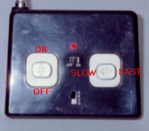
Diodes control either of the 2 relays connected in place of an original motor, so a total of 4 relays can be controlled by the circuit board, but with additional relays and some relay logic, we can get a few more functions when 2 levers are depressed concurrently. This controller has a switch for 4 different frequencies, so if you can buy 2 (or more) identical RC cars, then you can switch between frequencies from the same controller with extra boards for controlling turnouts or other layout features.
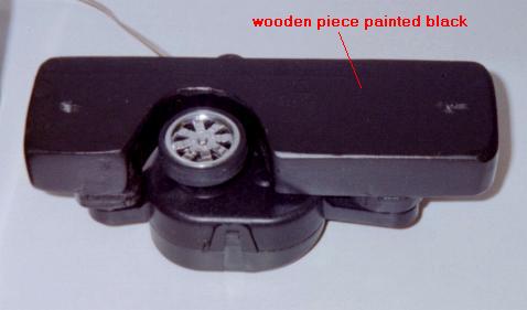
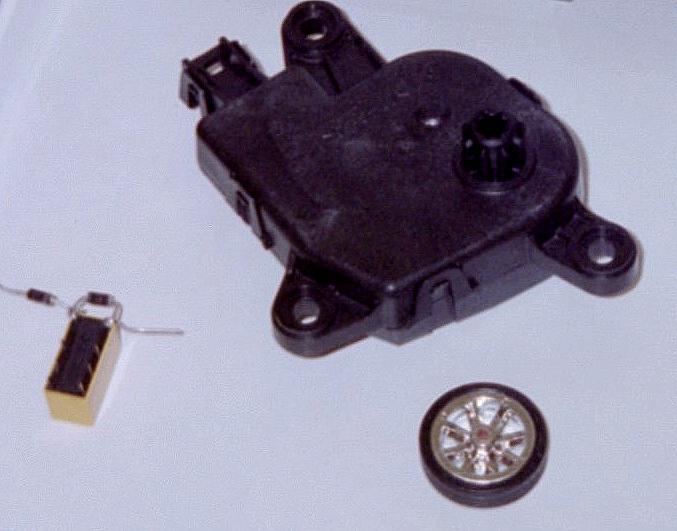
The motor is a 5 rpm 12 VDC grearhead DC motor, slowed even more by running it on only 3 VDC. A wheel's hub fits almost perfectly inside the bore of the motor's drive shaft. The bore was slightly enlarged with a common drill bit. Perhaps the most difficult part is in getting the wheel mounted to the motor's shaft so it is centered. But because the tire is on the soft side, if it were slightly off-center, it probably wouldn't matter. A spring could be used on the motor's housing to keep the wheel in constant tension against the throttle knob.
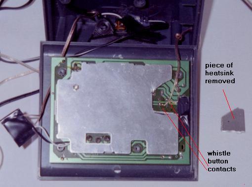
Notice that the latching is done by one pole of the relay's contacts keeping power to the coil after the initial activation. This allows for power to be kept on the rails when the controller's lever is released. Notice how the whistle (in the diagram above) is wired through 2 relays, and how the power to the throttle's motor is cut. So both the forward lever and the right lever need to be depressed for the whistle to fire. So, while depressing the forward lever, the right lever is depressed for the whistle, remembering to always do the operation in that order, or the throttle will advance for a brief moment if the right lever is depressed first. If it is possible to find 4PDT relays in 3 VDC, that would greatly simplify the wiring. More could be done by adding relays so 'forward' and 'left' would yield another function.