With the popularity and ease of using Bluetooth technology for wireless control of robotics, drones, model cars and planes, I wanted to try my hand at building a controller as a trackside throttle/transformer, or something on-board like the DCC decoders that are commercially available. In addition to a Bluetooth transceiver, you'll need a microcontroller like the
PicAxe. But this project isn't for just a throttle, but also for controlling turnouts/switches and other things on a layout that is currently conventionally controlled (with the exception of some automation from an old Timex/Sinclair computer with an I/O board). The control panel is dual wired so if the computer isn't used, manual control is possible without any fuss. The Bluetooth/Picaxe control will also allow for a manual/conventional control option. However, any on-board circuitry will need a physical on-board switch (bypassing the electronics) to allow for conventional control should the electronics fail or if they are not desired.
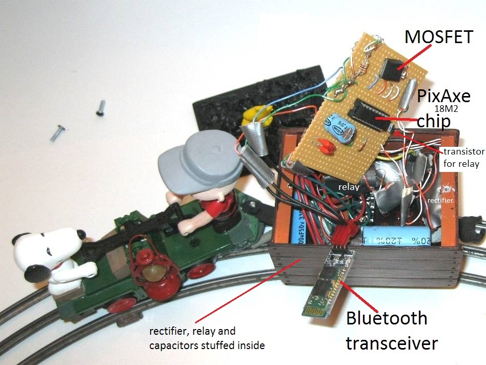
Many of my YouTube videos feature handcars, but the circuits are the same for small motorized items or large locomotives. The project has a MOSFET that will handle most large scale locomotives. The PWM does work with the older open-frame motors because they can run on AC or DC. DC will cause issues with any AC circuit that uses a DC offset, like the Lionel whistling tender circuit. But there are alternatives. I also built a throttle that applies variable AC on the tracks and the DC offset; it doesn't use PWM but rather pre-set AC voltages delivered by several relays. I have yet to test the PWM with a conventional mechanical e-unit or an electronic e-unit. Typically, the trackside PWM throttle wouldn't be used with any on-board electronics or decoders and the throttle might destroy them.
I would like to thank everyone on the Picaxe forum who answered many of my questions and helped me (and continue to help) with several technical issues.
Acquire a Picaxe 18M2 starter kit with the USB cable from one of the many suppliers that offer robotics and electronics hobby supplies. Familiarize yourself with the Picaxe starter kit, load the software and cable drivers, and use the simple project offered in their materials to get your feet wet with the system and project board. There is no substitute or shortcut for taking the time to learn the system. The diagrams and instructions below crystallize weeks of trial and error, sometimes frustrating work. The code can just be copied and pasted into the program editor. I learned BASIC Plus back in 1977 in college, however the Picaxe BASIC is not as robust. You'll need to learn to write code in Picaxe BASIC in order to customize this project or build different controllers.
The mystique surrounding Pulse-Width Modulation (PWM) causes much apprehension; it may seem too complicated to write the code and build the circuit. But the Picaxe chip and program editor eliminates the guesswork and allows for a very simple circuit with few components. The Picaxe 18M2 chip has a built-in PWM feature. And the Picaxe programming editor has a PWM wizard that figures the PWM code for you. In very simple terms, PWM delivers a fixed higher voltage in fast precise pulses that has an effect on a motor or light as if the voltage was varied, from zero to the maximum or any point in between, depending on your commands. So if 12VDC is pulsed very quickly so it is "on" half the time and "off" for the other half of the time, the motor behaves as if you supplied 6 VDC to it, for this overly simplified explanation. If you were to have the chip pulse 12VDC for 3 quarters of the time, the motor would behave as if you supplied 9 volts. (Search the internet for more information on PWM.) All that is needed, aside from the Picaxe chip, is a MOSFET (a type of transistor) to control a motor in a locomotive. The throttle circuit can be used trackside or on-board the train/loco. The PWM works on permanent magnet DC motors and most older universal (AC/DC) open-frame motors in Lionel and American Flyer locomotives. The other part of this project is the free Android app that allows you to create a touchscreen throttle (slider) that responds to a swipe of the finger. The RoboRemoFree
app is easy to configure and customize. Just remember to make sure you have the latest version. Then open 'menu' -- 'more options' -- 'RFCOMM settings' then choose "auto" and "default" and press "OK."
Lighting and LEDs can also be controlled (dimmed and brightened) by the same PWM code and MOSFET circuit.
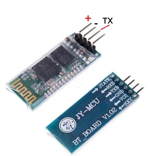
This is the HC-06 Bluetooth board; only 3 of the 4 headers are used. The TXD pin connects to the 18M2's C.0 pin. Power and ground
(approx. 5 VDC) is shared with microcontroller board.
The pins marked in red indicate those used for this simple project. Pin C.4 needs to be tied to ground with a 10k resistor. The others are the voltage in and out, B.6 is the PWM pin, B.4 for the relay, and the last one, C.0 for the Bluetooth transceiver (TXD). 2 small caps, first a tiny 100mfd 16 volt electrolytic, then a .22 mfd polyester cap need to filter the power to the chip and HC-06 board. Not difficult. Pin C.0 may benefit from being tied to ground with a 10k resistor also. "Floating" pins may cause issues.
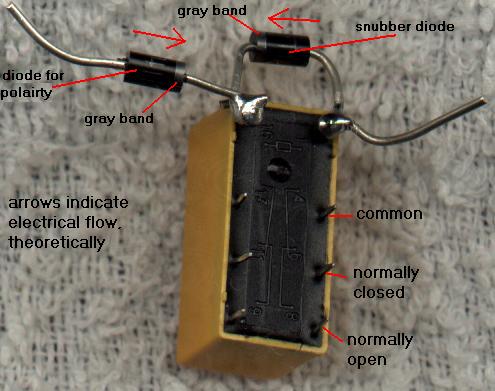
The MOSFET circuit is also simple. Just remember to use the cap to suppress electrical motor noise and the "snubber" diode to protect the circuit. The positive voltage for the motor is supplied from the higher rectified and filtered track voltage. A diode string of approx. 12 diodes cuts voltage by about 8 volts because the motor only needs a max of 14 VDC.
The relay uses a conventional model railroading technique to reverse polarity with a DPDT switch.
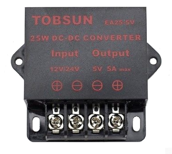
The purchased voltage regulator.
With about 16-18 VAC on the track, once rectified and filtered it yields about 22 VDC. The rectified voltage is filtered with a 3300 mfd 50 volt electrolytic capacitor before it enters the regulator. The 5 VDC output is then filtered with a 2200 mfd 35 volt electrolytic capacitor.
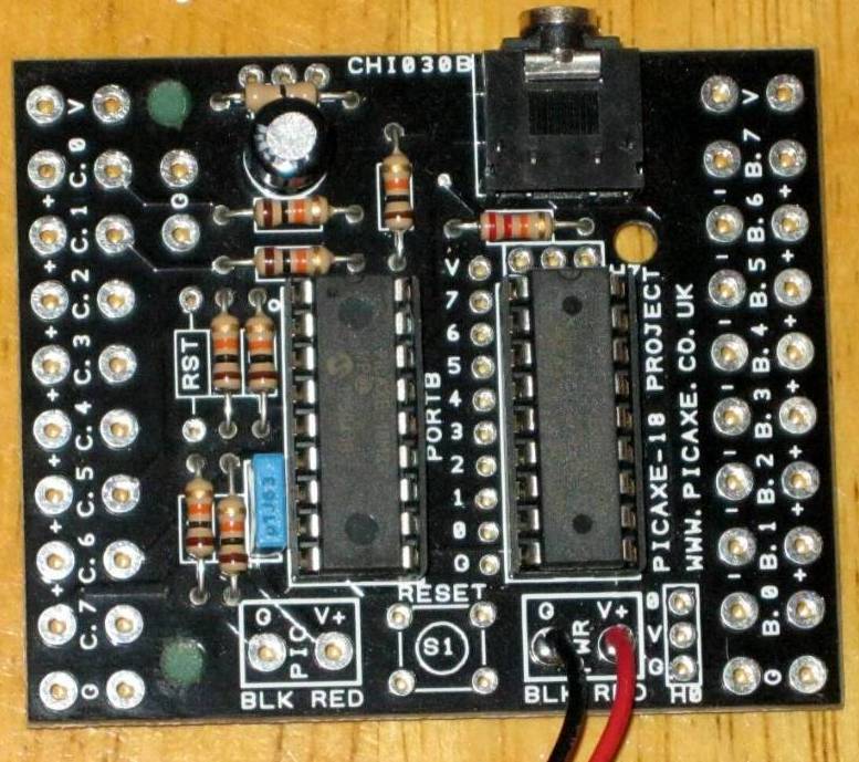
The ready-assembled board from the starter kit for the 18M2 Picaxe chip.
You can use this board and not bother to build your own. None of the pins float, they are already tied to ground, and the Darlington array eliminates the need for the transistor circuit for the relay. You will have to disable the pin on the Darlington array that corresponds to the PWM pin used. Either bend or break the pin off of the Darlington array from the left side of the array. Solder a wire to the correct port pad to the right of the 18M2 chip on the board for the MOSFET circuit. I use this board to program a chip that I will later move to the circuit I built on plain perforated board. Carefully pry up the Picaxe chip and be gentle with the tiny pins when inserting it into the socket on another board. Magnifying glasses are helpful, even if your vision is good. The IRL540N MOSFET might be a better choice than the one I used.
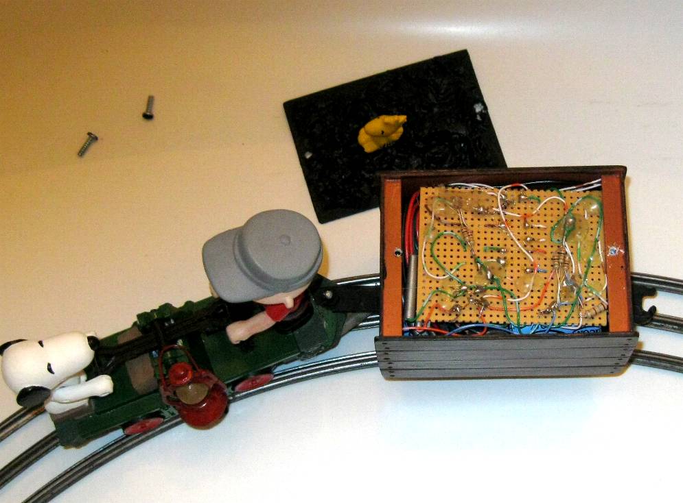
The project at a glance
Copy and paste this code into the Picaxe program editor. It works well-- see videos.
setfreq m8


main:


serin C.0, T9600_8,b0,b1


if b1 = 48 then goto zero           ;48 to 57 is ASCII for "0" to "9"


if b1 = 49 then goto one


if b1 = 50 then goto two


if b1 = 51 then goto three


if b1 = 52 then goto four


if b1 = 53 then goto five


if b1 = 54 then goto six


if b1 = 55 then goto seven


if b1 = 56 then goto eight


if b1 = 57 then goto nine


if b0 = 99 then goto Direction         ;99 is ASCII for lowercase "c"


if b0 = 109 then goto ZeroZero         ;109 is ASCII for lowercase "m"


if b0 = 110 then goto ZeroReset        ;110 is ASCII for lowercase "n"


goto main


zero:


pwmout B.6, OFF


Let b2=0


goto main


one:


pwmout B.6, 99, 200


Let b2=1


goto main


two:


pwmout B.6, 99, 225


Let b2=2


goto main


three:


pwmout B.6, 99, 250


Let b2=3


goto main


four:


pwmout B.6, 99, 275


Let b2=4


goto main


five:


pwmout B.6, 99, 300


Let b2=5


goto main


six:


pwmout B.6, 99, 325


Let b2=6


goto main


seven:


pwmout B.6, 99, 350


Let b2=7


goto main


eight:


pwmout B.6, 99, 375


Let b2=8


goto main


nine:


pwmout B.6, 99, 400


Let b2=9


Goto main


Direction:		     ; reverses leads to the tracks


pwmout B.6, OFF


pause 2000


toggle B.4


goto ZeroReset


ZeroZero:                 ;PWM OFF


 pwmout B.6, OFF


goto main


zeroReset:                ; for release of STOP/direction button


if b2=0 then goto Zero


If b2=1 then goto One


If b2=2 then goto Two


If b2=3 then goto Three


If b2=4 then goto Four


if b2=5 then goto Five


If b2=6 then goto Six


If b2=7 then goto Seven


If b2=8 then goto Eight


If b2=9 then goto Nine


    goto main
The Picaxe 18M2 program receives 2 characters sent from the remote with the SERIN line, then acts on them. Configure the remote to send "cc" to toggle the reversing relay (only the first character is used here, the second is not).
Sending "mm" will stop the motor, and "nn" will start it at the last speed used (only the first character is used here also).
Configure the app's slider for values of 0 to 9. For example, the app's slider sends "t5" for the motor to run at medium speed. (The first character can be any ASCII letter of your choice provided it isn't "m" "n" or "c". "0" is for no voltage flowing to the motor, and "9" is for the maximum.) The slider on the touchscreen remote sends a minimum of 2 characters to the Picaxe micro-controller, via the Bluetooth transceiver, at a time (follow the apps instructions); that is why the SERIN line has to receive 2 characters before it moves forward. All serial data sent from the remote must be in a 2 character format for this simplified program, but other methods are possible.
This is the same circuit, trackside, not contained inside the ore car. It does not include the components to rectify and filter track power because the powersupply is a 12 VDC regulated wall transformer.
Have Fun!!!!!
The site owner is not and cannot be held liable for fire, electrical shock, property damage, bodily injury, loss of life, or accident of any kind caused by electrical circuits or any ideas, projects, techniques, or information contained on this site.
The visitor assumes all risk and responsibility for any loss, injury, accident or damage arising from the use of information, ideas, techniques, projects, concepts, components, products, and circuits on this site.
Please refer to hobby reference materials for correct and safe use information
regarding these and all electronic circuits. These diagrams are intended to explain how things were accomplished in theory, but it is the
responsibility of the individual to locate precise information regarding electrical circuits, materials, ratings of components, etc. Do not attempt
these hobby projects, or any electrical project, if you don't have the necessary skills and experience.