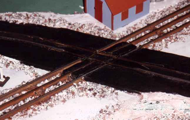
Gargraves O gauge 3 rail flex track (with
blackened center rail) is used here for
the insulated rails before and after the
crossing, and another Gargraves section is used to
release the stopped vehicle about 10 feet
away.
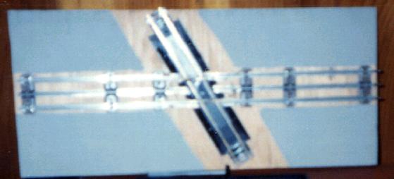
Here is how the HO/O27 crossing began.
It is Lionel O27 track and brass HO rerailer track
shimmed up to 3 rail height. Just maintain the proper flangeway for
each gauge.
Please refer to hobby reference materials for correct and safe use information
regarding these and all electronic circuits. These diagrams are intended to explain how things were accomplished in theory, but it is the
responsibility of the individual to locate precise information regarding electrical circuits, materials, ratings of components, etc. Do not attempt
these hobby projects, or any electrical project, if you don't have the necessary skills and experience. The page owner is not and cannot be held responsible
for fire, electrical shock, damage, or accident of any kind
caused by these circuits or any ideas or information contained on this site.
This shows how the reed switch, activated
by a magnet glued under the vehicle, will energize the relay,
which removes DC from the HO rails
(stopping the vehicle's motor) and applies HF AC in its place.
An insulated section of O27 track about 10
feet away will break the latching of this relay, letting the vehicle resume.